Tri-Core Fusion Processor
The Ensemble E5 is a fusion processor: a new category of embedded controllers that blend MPU, MCU, and AI/ML into a single device. Its dual Cortex-M55 CPUs, one configured to maximize power efficiency and the other to maximize compute performance, dual Ethos-U55 NPUs to accelerate AI/ML operations, and one Cortex-A32 Application CPU core for high level operating systems like Linux, makes the E5 series ideal for applications such as home automation, smart lighting, security cameras, or industrial control systems.
Key Benefits of E5:
-
Linux & RTOS for efficient balance of application and real-time processing
-
Rich user interface, hi-perf networking
E5 Specifications
- Arm Cortex®-A32 Core with Arm Neon™ SIMD Extension up to 800 MHz, 512KB Shared L2, 32KB L1 Instruction and Data Caches, MMU,
Armv8-A ISA with Arm TrustZone® - High-Performance Arm® Cortex®-M55 Core, up to 400 MHz, with Helium™ Vector Processing Extension, Double-Precision FPU, 1.25MB SRAM 0-wait State Tightly- Coupled Memory, 32KB Instruction and Data Caches, Armv8.1-M ISA with Arm TrustZone®, and 4.37 CoreMark®/MHz Performance Benchmark
- Arm® Cortex®-M55 Core, up to 160 MHz, with Helium™ Vector Processing Extension, DoublePrecision FPU, 512KB of SRAM 0-wait State Tightly Coupled Memory, 32KB Instruction and Data Caches, Armv8.1-M ISA with Arm TrustZone®, and 4.37 CoreMark®/MHz Performance Benchmark
- High-Performance 400-MHz 64-bit AXI Bus Fabric Common Across All CPUs

- 2× Arm Ethos™-U55 Neural Processing Units— 1× 256 MAC/cycle up to 204 GOPS, 1× 128 MAC/cycle up to 46 GOPS, On-the-Fly Weight Decompression with Dedicated DMA Controller
- 800× Performance Uplift from Cortex-M4 for Inference Time (Source: Arm. MobileNet V2 1.0 Model for Object Classification)
- 76× Less Energy Consumed when Using Ethos-U55 Together with Cortex-M55 (Source: Arm. Measured on Alif Semiconductor Ensemble Device. MobileNet V2 1.0 Model for Object Classification)
- Autonomous Intelligent Power Management (aiPM™)
- FD-SOI Low Leakage Process
- 1.7 µA Consumed in STOP Mode with LPRTC, LPTIMER, LPCMP, BOR, 4KB Utility SRAM, Wake Pins
- As Low as 27 µA/MHz Dynamic Consumption for High-Efficiency Cortex-M55
- Multiple Power Domains, Dynamic Power, Gating, Voltage and Clock Scaling, DC-DC Converter
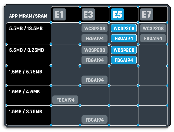
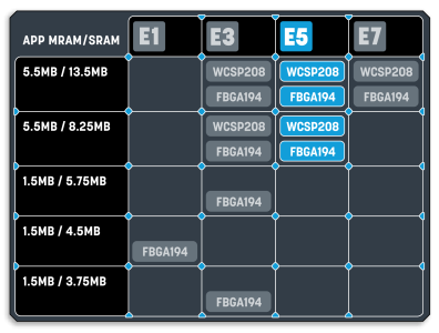
- High Endurance MRAM Non-Volatile Memory
- Up to 5.5MB
- SRAM
- Up to 13.5MB
- Optional Data Retention of 256KB or 512KB TCM SRAM Consuming 2.25 μA or 4.5 μA
- 4KB Always-On Utility SRAM
- 2× Octal SPI, each at up to 100 MHz for up to 100 MB/s SDR, 200 MB/s DDR, with Inline AES Decryption, XIP Mode Support, HyperBus Protocol Support, Enabling External Memory Expansion
- 1× SD® v4.2, eMMC™ v5.1 Channel with DMA
- Hardware-based Root-of-Trust (RoT) with Unique Device ID
- Secure Key Generation and Storage, Secure Certificate Storage
- Factory-provisioned Private Keys
- Crypto Accelerators—AES (up to AES-256), ECC (up to 384 bits), SHA (up to SHA-256), RSA (up to RSA-3072), and NIST compliant TRNG
- Secure Debugging with Certificate Authentication
- 12× Universal High-Resolution 32-bit Timers
- Capable of Motor and LED Lighting Control
- 4× Watchdog Timers
- 4× Low-Power 32-bit Timers
- 1× Real-Time Counter
- 4× Quadrature Encoder Counters
- 1× 10/100 Ethernet with DMA
- 1× USB 2.0 HS/FS Host/Device with DMA
- 1× SDIO v4.1 Channel with DMA
- 1× CAN FD Channel up to 10 Mbps
- 1× MIPI® I3C® Channel
- 4× I2C Channels up to 3.4 Mbps Throughput
- 1× Low-Power I2C Channel
- 8× UART Channels up to 2.5 Mbps (4× with RS485 Driver Control)
- 1× Low-Power UART Channel
- 4× SPI Channels up to 50 Mbps Throughput
- 1× Low-Power SPI Channel
- 3× 12-bit ADC (18 Single-Ended Inputs)
- 1× 24-bit ADC (4 Differential Inputs)
- Programmable Gain Instrumentation Amplifier (1× to 128×)
- 2× 12-bit DACs (2 channels)
- 4× High-Speed Analog Comparators with 2.5-ns Response (16 Inputs)
- 1× Low-Power Analog Comparator (4 Inputs)
- Internal Temperature Sensor
- Internal Precision Reference Voltage
- 1× 2-Lane MIPI CSI-2®
- 1× Camera Parallel Interface (CPI), up to 16 bits
- 1× Low-Power CPI, up to 8 bits
- Graphics LCD Controller
- 1× Display Parallel Interface (DPI), up to 24-bit RGB
- 1× 2-Lane MIPI DSI®
- D/AVE 2D Graphics Processing Unit
- 4× I2S Synchronous Stereo Audio Interfaces
- 1× Low-Power I2S Stereo Audio Interface
- 4× 2-channel Pulse Density Modulation (PDM) Microphone Inputs (8 Mono Microphones)
- 4× 2-channel Low-Power Pulse Density Modulation (LPPDM) Microphone Inputs (8 Mono Microphones)
- Up to 120× 1.8-V GPIOs (Shared with Peripherals)
- Up to 8× Selectable 1.8-V to 3.3-V GPIOs (Shared with Peripherals)
- Internal Low-Frequency RC Oscillator (32.7 kHz, ±4%)
- Internal High-Frequency RC Oscillator (Up to 76.8 MHz, ±1%)
- External High-Frequency Crystal Oscillator or Quartz Crystal (24 MHz to 38.4 MHz)
- External Low-Power Crystal Oscillator or Quartz Crystal (32.768 kHz)
- One User Fractional Mode PLL
- Global Event Mapping to Configurable Triggers
- 3× 32-Channel General DMA Controllers
- CRC Calculation Accelerator with Programmable Polynomials
- Programmable Low Supply Voltage Detect Warning (Brown-Out Detect)
- Power-On Reset and Brown Out Reset
- Real-Time Clock
- JTAG/SWD Debug Interface
- 1.75 V to 4.2 V Primary Supply Range
- 1.08 V to 1.98 V I/O Supply Range (1.8 V I/O)
- 3.0 V to 4.2 V I/O Supply Range (3.3 V Flex I/O)
- -40 °C to 75 °C Extended Ambient Temperature Range
- -40 °C to 105 °C Extended Junction Temperature Range
- WLCSP208, 0.5 mm Pitch
- FBGA194, 0.5 mm Pitch
High-Performance Tri-Core Fusion Processor
- Arm Cortex®-A32 Core with Arm Neon™ SIMD Extension up to 800 MHz, 512KB Shared L2, 32KB L1 Instruction and Data Caches, MMU,
Armv8-A ISA with Arm TrustZone® - High-Performance Arm® Cortex®-M55 Core, up to 400 MHz, with Helium™ Vector Processing Extension, Double-Precision FPU, 1.25MB SRAM 0-wait State Tightly- Coupled Memory, 32KB Instruction and Data Caches, Armv8.1-M ISA with Arm TrustZone®, and 4.37 CoreMark®/MHz Performance Benchmark
- Arm® Cortex®-M55 Core, up to 160 MHz, with Helium™ Vector Processing Extension, DoublePrecision FPU, 512KB of SRAM 0-wait State Tightly Coupled Memory, 32KB Instruction and Data Caches, Armv8.1-M ISA with Arm TrustZone®, and 4.37 CoreMark®/MHz Performance Benchmark
- High-Performance 400-MHz 64-bit AXI Bus Fabric Common Across All CPUs
Efficient Micro NPUs for AI/ML Acceleration
- 2× Arm Ethos™-U55 Neural Processing Units— 1× 256 MAC/cycle up to 204 GOPS, 1× 128 MAC/cycle up to 46 GOPS, On-the-Fly Weight Decompression with Dedicated DMA Controller
- 800× Performance Uplift from Cortex-M4 for Inference Time (Source: Arm. MobileNet V2 1.0 Model for Object Classification)
- 76× Less Energy Consumed when Using Ethos-U55 Together with Cortex-M55 (Source: Arm. Measured on Alif Semiconductor Ensemble Device. MobileNet V2 1.0 Model for Object Classification)
Extreme-Low Power Technology
- Autonomous Intelligent Power Management (aiPM™)
- FD-SOI Low Leakage Process
- 1.7 µA Consumed in STOP Mode with LPRTC, LPTIMER, LPCMP, BOR, 4KB Utility SRAM, Wake Pins
- As Low as 27 µA/MHz Dynamic Consumption for High-Efficiency Cortex-M55
- Multiple Power Domains, Dynamic Power, Gating, Voltage and Clock Scaling, DC-DC Converter
On-Chip Application Memory
- High Endurance MRAM Non-Volatile Memory
- Up to 5.5MB
- SRAM
- Up to 13.5MB
- Optional Data Retention of 256KB or 512KB TCM SRAM Consuming 2.25 μA or 4.5 μA
- 4KB Always-On Utility SRAM
External Memory Interfaces
- 2× Octal SPI, each at up to 100 MHz for up to 100 MB/s SDR, 200 MB/s DDR, with Inline AES Decryption, XIP Mode Support, HyperBus Protocol Support, Enabling External Memory Expansion
- 1× SD® v4.2, eMMC™ v5.1 Channel with DMA
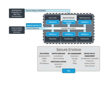
Secure Enclave
- Hardware-based Root-of-Trust (RoT) with Unique Device ID
- Secure Key Generation and Storage, Secure Certificate Storage
- Factory-provisioned Private Keys
- Crypto Accelerators—AES (up to AES-256), ECC (up to 384 bits), SHA (up to SHA-256), RSA (up to RSA-3072), and NIST compliant TRNG
- Secure Debugging with Certificate Authentication

Timing Control and Measurement
- 12× Universal High-Resolution 32-bit Timers
- Capable of Motor and LED Lighting Control
- 4× Watchdog Timers
- 4× Low-Power 32-bit Timers
- 1× Real-Time Counter
- 4× Quadrature Encoder Counters
Serial Communication Interfaces
- 1× 10/100 Ethernet with DMA
- 1× USB 2.0 HS/FS Host/Device with DMA
- 1× SDIO v4.1 Channel with DMA
- 1× CAN FD Channel up to 10 Mbps
- 1× MIPI® I3C® Channel
- 4× I2C Channels up to 3.4 Mbps Throughput
- 1× Low-Power I2C Channel
- 8× UART Channels up to 2.5 Mbps (4× with RS485 Driver Control)
- 1× Low-Power UART Channel
- 4× SPI Channels up to 50 Mbps Throughput
- 1× Low-Power SPI Channel
Analog Interface Capabilities
- 3× 12-bit ADC (18 Single-Ended Inputs)
- 1× 24-bit ADC (4 Differential Inputs)
- Programmable Gain Instrumentation Amplifier (1× to 128×)
- 2× 12-bit DACs (2 channels)
- 4× High-Speed Analog Comparators with 2.5-ns Response (16 Inputs)
- 1× Low-Power Analog Comparator (4 Inputs)
- Internal Temperature Sensor
- Internal Precision Reference Voltage
Camera Interfaces
- 1× 2-Lane MIPI CSI-2®
- 1× Camera Parallel Interface (CPI), up to 16 bits
- 1× Low-Power CPI, up to 8 bits
Display Interfaces & Graphics
- Graphics LCD Controller
- 1× Display Parallel Interface (DPI), up to 24-bit RGB
- 1× 2-Lane MIPI DSI®
- D/AVE 2D Graphics Processing Unit
Audio Interfaces
- 4× I2S Synchronous Stereo Audio Interfaces
- 1× Low-Power I2S Stereo Audio Interface
- 4× 2-channel Pulse Density Modulation (PDM) Microphone Inputs (8 Mono Microphones)
- 4× 2-channel Low-Power Pulse Density Modulation (LPPDM) Microphone Inputs (8 Mono Microphones)
General Input/Output
- Up to 120× 1.8-V GPIOs (Shared with Peripherals)
- Up to 8× Selectable 1.8-V to 3.3-V GPIOs (Shared with Peripherals)
Clock Generation
- Internal Low-Frequency RC Oscillator (32.7 kHz, ±4%)
- Internal High-Frequency RC Oscillator (Up to 76.8 MHz, ±1%)
- External High-Frequency Crystal Oscillator or Quartz Crystal (24 MHz to 38.4 MHz)
- External Low-Power Crystal Oscillator or Quartz Crystal (32.768 kHz)
- One User Fractional Mode PLL
System
- Global Event Mapping to Configurable Triggers
- 3× 32-Channel General DMA Controllers
- CRC Calculation Accelerator with Programmable Polynomials
- Programmable Low Supply Voltage Detect Warning (Brown-Out Detect)
- Power-On Reset and Brown Out Reset
- Real-Time Clock
- JTAG/SWD Debug Interface
Operating Parameters
- 1.75 V to 4.2 V Primary Supply Range
- 1.08 V to 1.98 V I/O Supply Range (1.8 V I/O)
- 3.0 V to 4.2 V I/O Supply Range (3.3 V Flex I/O)
- -40 °C to 75 °C Extended Ambient Temperature Range
- -40 °C to 105 °C Extended Junction Temperature Range
Packages
- WLCSP208, 0.5 mm Pitch
- FBGA194, 0.5 mm Pitch