

1. Introduction
Embedded system designs are often faced with the challenge of balancing many contradictory requirements: high performance and low power consumption, device versatility and low latency, as well as security and application flexibility. Alif Semiconductor addresses these design constraints with dynamic and highly scalable microcontrollers (MCUs) that actively optimize all aspects of its core function including processing, power management, security, memory, hardware acceleration, connectivity, and software reuse. Alif’s secure system architecture ensures all devices are secure from the ground up allowing designers complete control over the security in their embedded systems.
This whitepaper discusses Alif Semiconductor’s “Secure Enclave”: an independent, isolated security subsystem as well as Alif’s secure 4-stage lifecycle management. Furthermore, we will discuss how this builds on conventional measures to ensure endpoint device security against common threats (e.g., malware, data theft, network breach, IP theft, cloning, rollbacks) such as TrustZone, Root of Trust, etc., with unique security services and a flexible configuration matrix.
2. Threats in the Landscape of IoT Devices
As shown in Figure 1, the potential threats to deployed IoT devices are numerous. From malware, where attackers may insert malicious code to hijack devices; to network breaches, where somebody may spoof an authentic, secure site with the ulterior motive of gaining access to secure information. There are other threats as well for edge devices: data theft can occur when an attacker bypasses encryption or breaches memory protection to steal sensitive data, valuable code, or intellectual property (IP). Device manufacturers will also have to consider the possibility that an attacker will copy device identity to illegally manufacture units and steal any potential revenue. In rollback attacks, the devices in the field rollback to an earlier version of firmware that might have a known security weakness to exploit the system. Device manufacturers and OEMs must constantly consider the number and severity of security vulnerabilities.
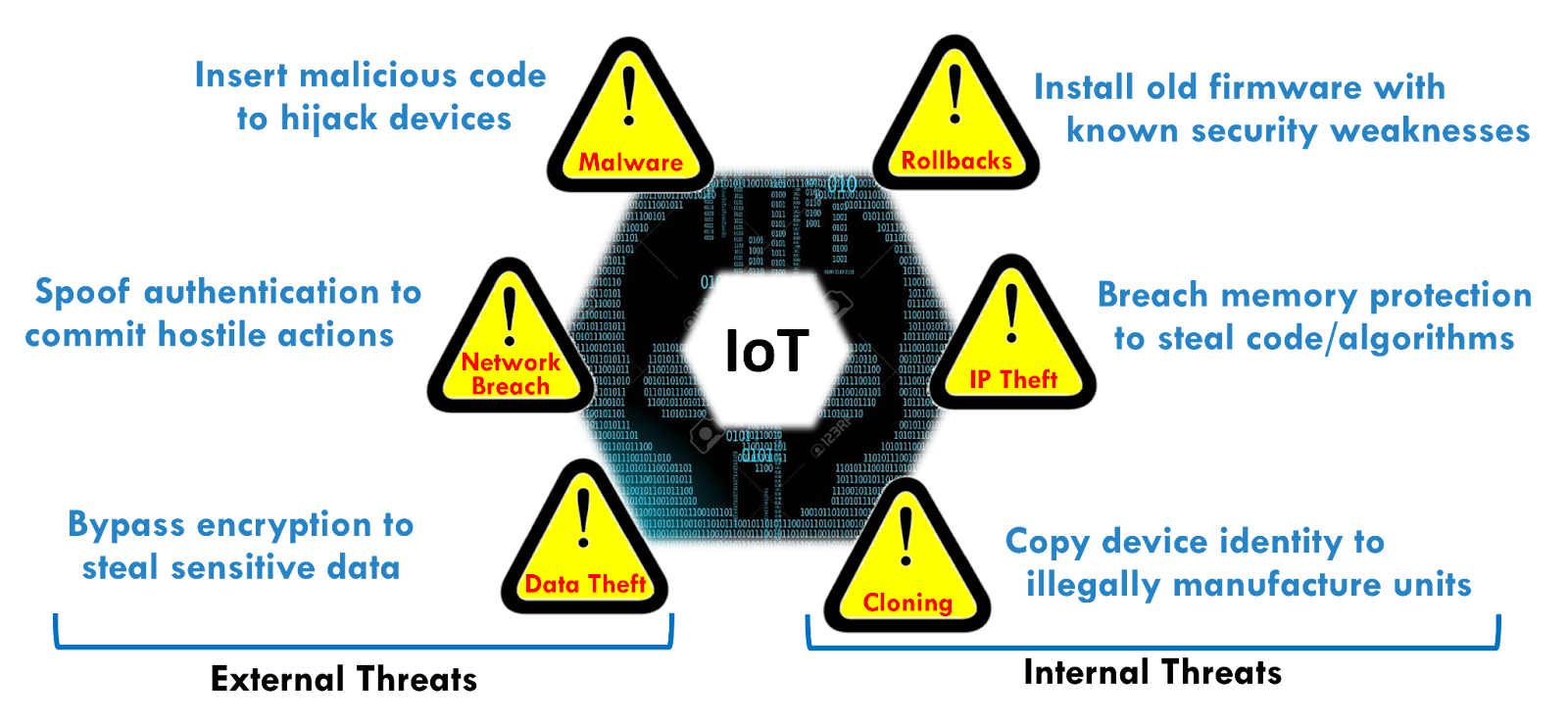
Figure 1: There are numerous IoT threats that can occur both internally and externally to an organization.
3. System Architecture
Alif’s MCUs can be scaled up starting from single-core MCUs to dual-core MCUs, and triple-core MCU/MPU fusion processors to quad-core MCU/MPU fusion processors. This allows Alif Semiconductor processors to match the needs of the specific embedded application. This scalable performance can be seen in Figure 2.
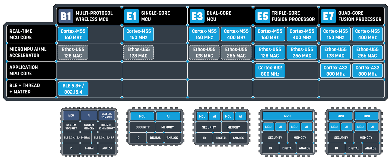
Figure 2: The Ensemble® and Balletto™ families offer scalable system performance, with Ensemble going from single-core MCUs to more complex quad-core MCU/MPU “fusion” processors.
The top-level system architecture for the E7 Ensemble MCU can be seen in Figure 3. This illustrates the basic architecture that Alif deploys to enable dynamic and scalable performance with a secure backbone. There are multiple subsystems — the secure enclave subsystem (SESS), application processing subsystem (APSS), real-time subsystem high-efficiency (RTSS-HE), real-time subsystem high-performance (RTSS-HP) — where each subsystem may have 1-2 CPUs, an optional NPU, as well as memory and peripherals integrated. This whitepaper will discuss the SESS subsystem in more detail.
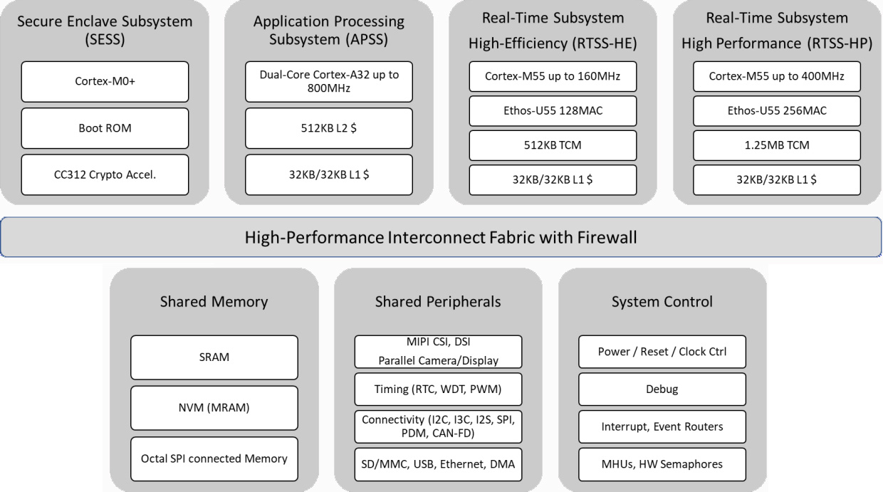
Figure 3: Top level system architecture of the E7 series. [Source: Section 2 of Fusion Processor System Architecture]
These subsystems may also share a power domain and can access shared global memory and shared peripherals, but can execute code independently of the other subsystems. The backbone of the entire system is based upon a “high-performance interconnect fabric” that is secured by a number of firewalls that will monitor all master and slave ports on the bus. These firewalls can filter transactions based upon the desired security policy (Figure 4). Firewalls, controlled by the Secure Enclave, will configure the security policy to enable access to specific bus masters. The firewalls essentially perform the role of a TrustZone-compliant Peripheral Protection Controller.
Figure 4: The firewall architecture for Ensemble devices. [Source: Section 6 of Fusion Processor System Architecture]
4. Secure Enclave Architecture
Alif Semiconductor builds security into its devices from the ground up and at the heart of this is an isolated and independent security subsystem known as the secure enclave, or SESS. As shown in Figure 5, the SESS protects all assets within the chip including the CPU cores, memory and data interfaces, as well as code and IP. The SESS contains its own dedicated: CPU core, memory (ROM and SRAM with retention), one-time-programmable (OTP) memory, cryptographic hardware for functions such as calculating hash codes and performing signature checks, and holds the hardware-based Root of Trust for the device. Each chip receives a unique device ID and Key Pair where the SESS manages immutable key storage.
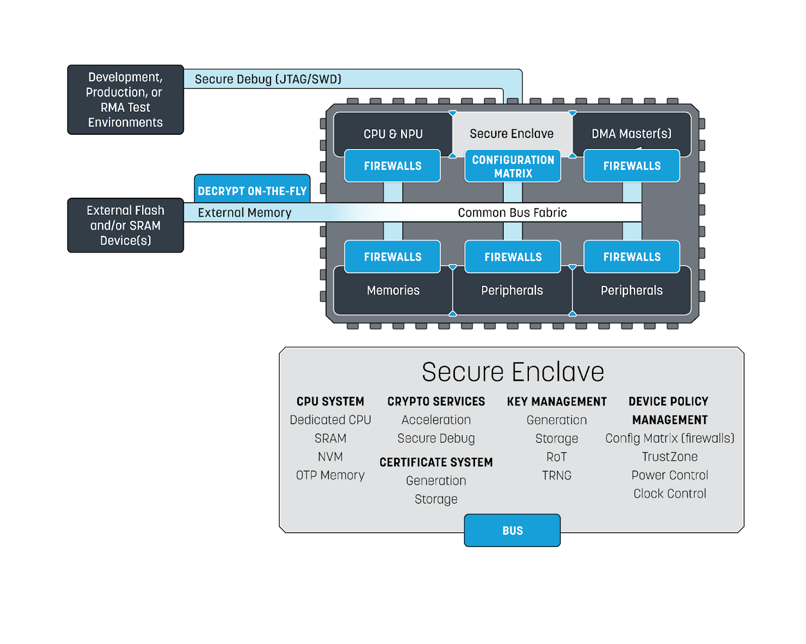
Figure 5: The independent, isolated security subsystem featured in Alif Semiconductor’s chips that contains its CPU system, key system, crypto services, certificate system, as well as device policy management.
The SESS regulates policy for the entire device and is isolated from the main interconnect fabric, so it is not accessible by running application code. As an example, a basic block diagram of the Inter-Process Communications (IPC) for the four subsystems (SESS, APSS, RTSS-HP, and RTSS-HE) within the Ensemble family can be seen in Figure 6. It has configurable firewalls that regulate access for each of the CPUs or DMA masters on the chip to sections of memory and individual peripherals; this supports and extends the capabilities of TrustZone. The SESS also provides on the fly decryption of memory external to the device (flash or SRAM). The secure enclave also has the ability to have a secure debug channel through JTAG or a serial device.
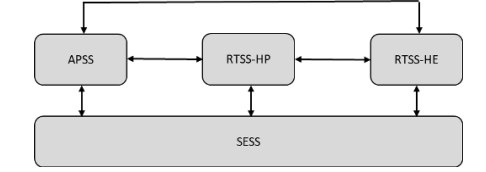
Figure 6: IPC topology for the Ensemble family of fusion processors (E5 to E7). [Source: Section 8 of Fusion Processor System Architecture]
As shown in Figure 7, service requests to the SESS are sent over a dedicated IPC logic called the Message Handling Unit (MHU). The MHU provides message passing between processors residing in different power and clock domains. After power up, the Secure Enclave performs a secure boot function, and after configuring the different security policies and firewall settings, starts the CPUs in the order specified by the designer.
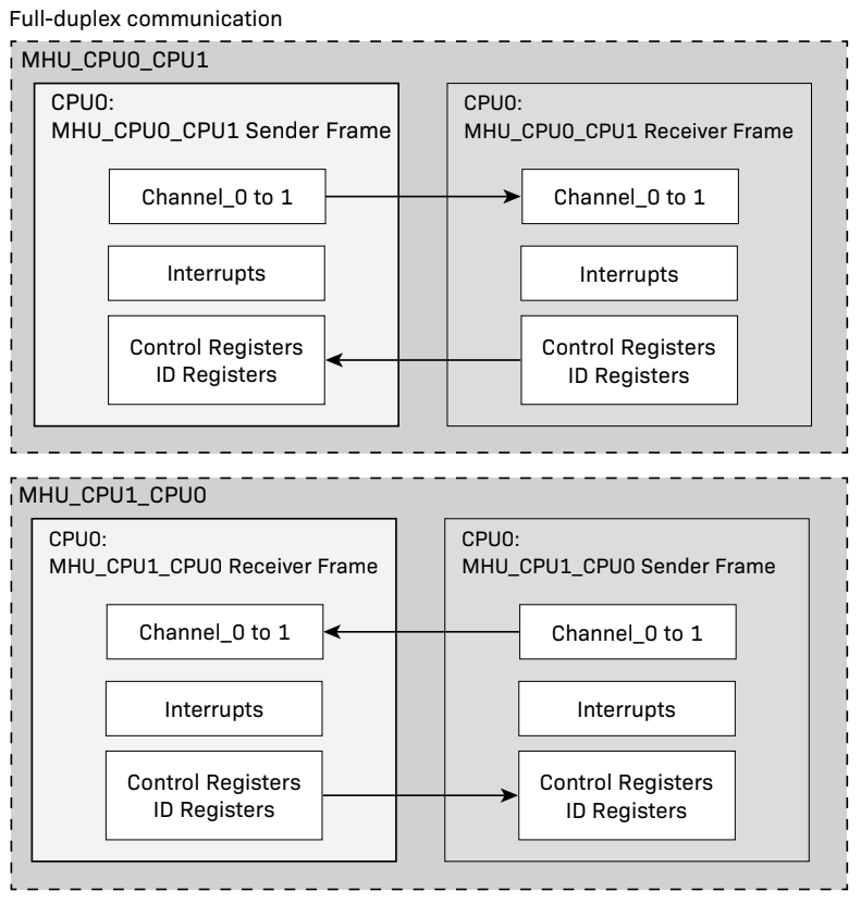
Figure 7: The MHU provides full duplex communication between the Secure Enclave and other subsystems and between the subsystems themselves.
5. Secure Lifecycle States (LCSs)
Alif Semiconductor also implements a secure four-state lifecycle process for its devices, this is managed by the SESS (Figure 8). It is a monotonic incrementing lifecycle system where it is impossible to move backwards or skip a step. When Alif initially manufactures the device, the device is in the “Device Manufacture” state where Alif tests the devices, provisions them with a unique ECC Key Pair and device ID, and programs signed device certifications. Most of the testing and development will occur in the “OEM Provisioning” or “Development” state. In this state, debugging and device programming are fully enabled and the firewalls are open. After the designer decides what the security environment will look like, the lifecycle state (LCS) can advance to the next deployment state.
The “Deployment” or “Secure” state typically occurs when the device is in the field. At this point, OEM keys are present and the device is secure. OEMs can select to have secure debug enabled and signed software updates can occur. Also in “Deployment”, any firewall configuration selected during development will be active, controlling security within the device.
If an OEM desires, they can advance the LCS to “End of Life” through a developer-signed certificate. In this state, all OEM keys and certificates are wiped out, code and data can also be wiped as well. The device is completely non-operational and the Secure Enclave will no longer continue the secure boot process and start any of the CPU cores. At this point, the device can also be shipped back to Alif for return materials authorization (RMA) and analysis if necessary.
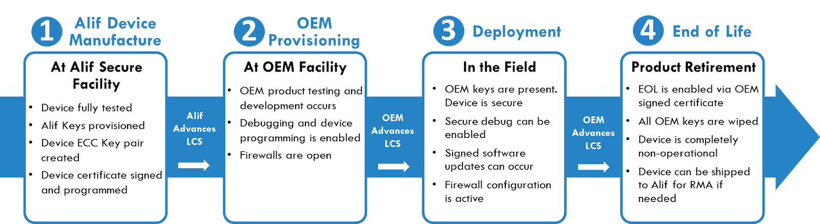
Figure 8: The four secure LCS’ that offer inherent protection against rollback attacks.
6. Going Beyond the TrustZone Security Model
Due to the use of a multi-core architecture in its chips, Alif had to consider going beyond the TrustZone model. In this model, an NS bit controls access by a CPU to either non-secure or secure areas of memory and peripherals (Figure 9). If NS Bit = 0, that section of code is allowed to access secure memory or peripherals, if NS Bit = 1 that section of code can only access non-secure application domains. This works well in a single-core system, however, in a multi-core system there is no way to grant exclusive secure domain access to one or the other CPU core. In other words, since there is only one bit, it is possible to have two CPU cores with secure code that can access the same secure domain, so any secrets will be shared.
The Alif multi-core security model where there is configurable security logic and firewalls that allow designers to control access to memory or peripherals as: exclusive to a specific CPU (CPU 1), shared between two CPUs (CPU 1 & 2), or shared with all the CPUs (All CPUs). The TrustZone bit can also be used and combined with the firewall logic to restrict access to a specific area of memory. This can be seen to the right in Figure 9 under “Only TrustZone Secure”, implying that this area is only coming from the CPU with its TrustZone secure code. The Alif multi-core security model controls access to different CPU cores to different memory and peripherals, which is critical in order to reduce the attack surface and keep highly sensitive areas isolated as much as possible.
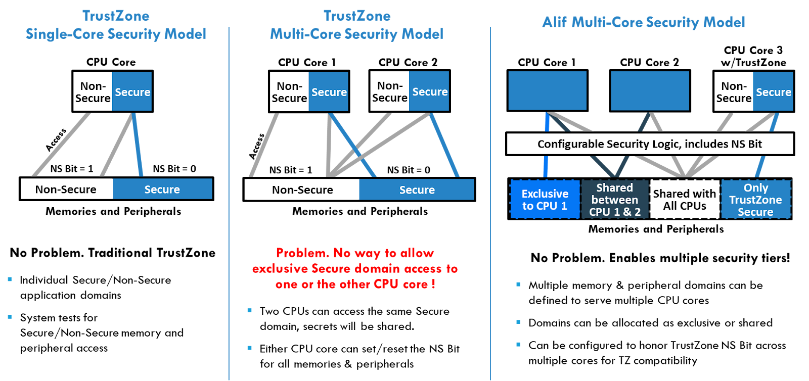
Figure 9: The TrustZone security model for single-core system (left) and a multi-core system (middle). The Alif multi-core security model (right) enables multiple security tiers, addressing the drawbacks of TrustZone.
7. Diving Into the Secure Enclave Subsystem’s Boot Process
As stated in section 5, after reset, the SESS performs the initial system configuration of the device and security boots applications subsystems during this time, all other subsystem application cores are held in a wait state until the SESS releases them. After the boot process is complete, the SESS can respond to service runtime requests for security, crypto, and power management (i.e., aiPM functions).
Provisioning is the ability to add images to the internal NVM storage (MRAM) and the ability to add security assets (e.g., Keys to OTP memory). Alif images are known as the system table of contents (STOC). The STOC contains pre-built binary images for the STOC package and the latest binary version of secure enclave RAM (SERAM). User images, such as applications programs, need to be packed and written into the MRAM. These packages are known as the application table of contents (ATOC) — a data structure located at the top address of the developer’s MRAM. The ATOC will contain the information that is used by the SE to initialize the device prior to booting any application core. The ATOC provides the user with full flexibility to:
- Configure the start sequence for application cores from which memory address
- Select whether signature validation should be performed or not
- Define where in memory the images are located
- Define how the pin-mux and clock tree should be configured
- Set up and apply the configuration matrix settings
Note, if the device is in the “Secure” LCS, then the ATOC must facilitate the secure boot process. If the device is in the “Development” LCS then the ATOC is optional. As shown in Figure 10, Alif provides a web-based configuration tool called “Conductor” that assists the user in creating the ATOC.
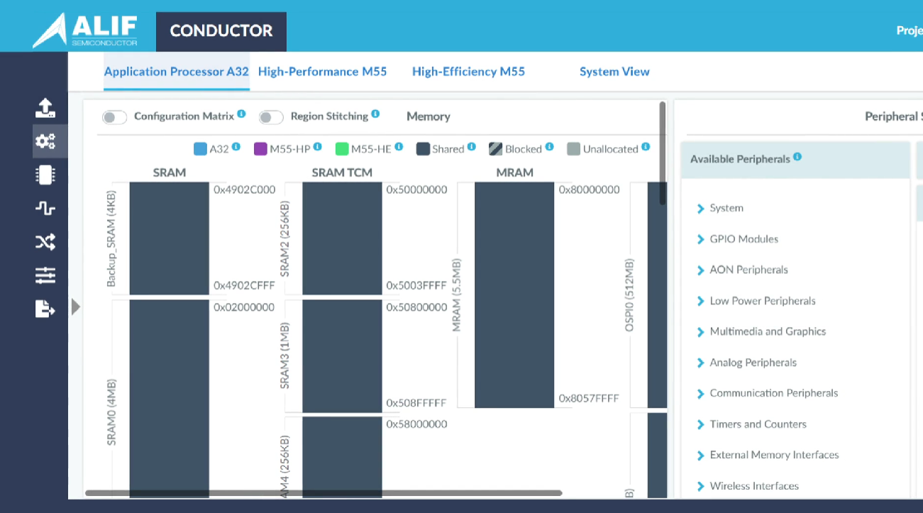
Figure 10: The web-based configuration tool, Conductor, that assists the user in creating the ATOC.
The boot process can be seen in Figure 11. After power is applied to the MCU, or a wakeup event occurs, the Secure Enclave will boot its first state from the secure ROM, which cannot be modified (See Figure 9 “SE Boots from SEROM” block). If the Secure Enclave is waking up from a low power mode with its SERAM retained, it can skip SERAM validation. If this is a powerup with no SERAM retained, it will load its second stage from secure nonvolatile MRAM and validate it. When the system is configured for warm boot, the Secure Enclave will immediately release the high efficiency subsystem to boot from retained memory, or MRAM, and then continue to load the secure MRAM image. During a warm boot, no application signature validation will be performed, and therefore the warm boot option is not available in the secure lifecycle state.
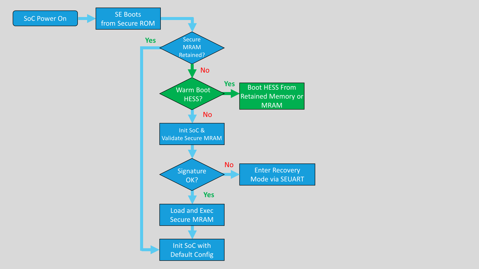
Figure 11: Warm boot process allows the system to boot from retained memory.
In a normal boot the system will verify the secure MRAM image signature and load the image into the Secure Enclave and begin execution.
If the Secure MRAM image signature validation fails, the boot process will stop and the device will enter into recovery mode; which allows a new correctly signed image to be loaded into the system through the Secure Enclave UART (SEUART).
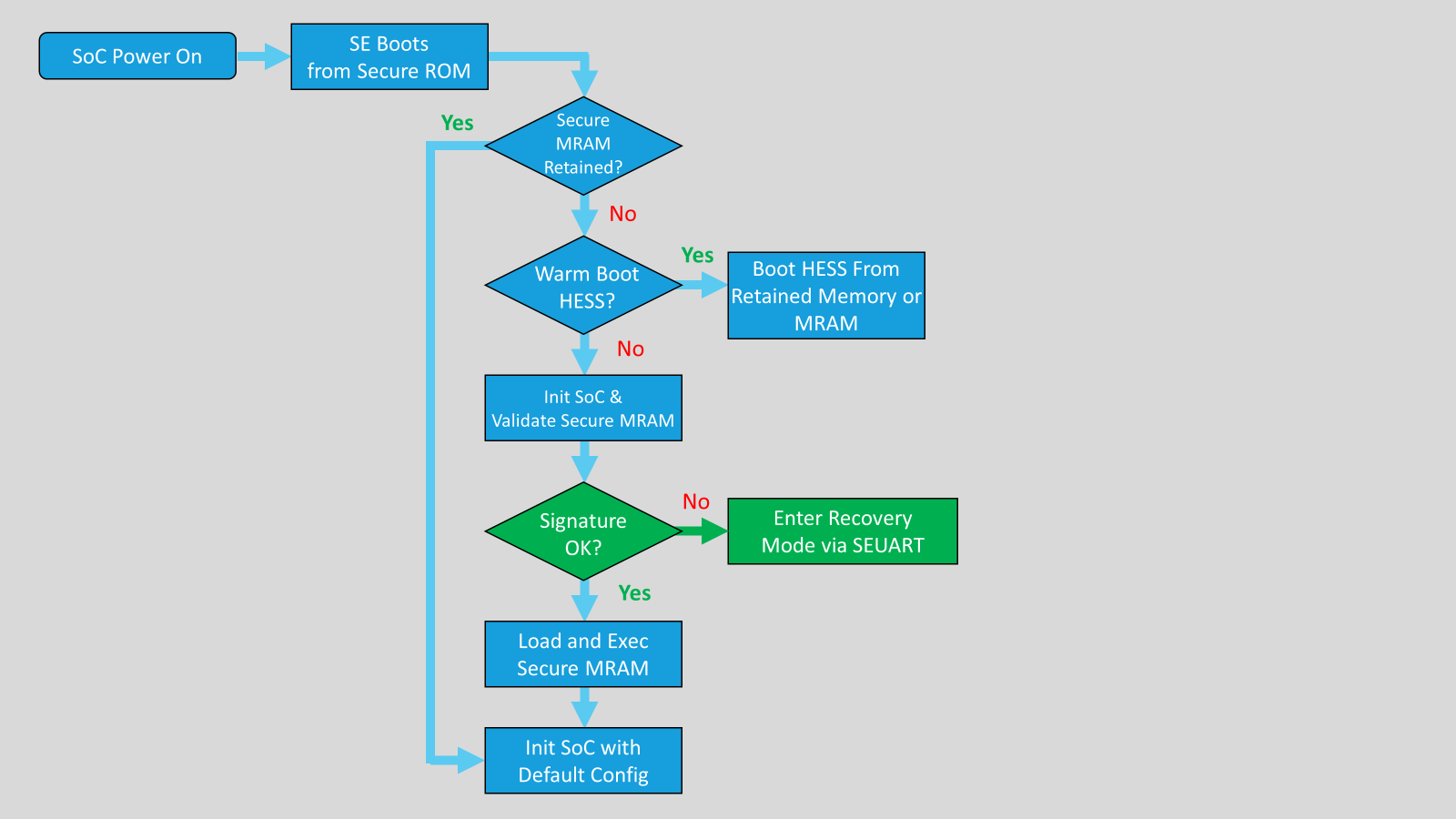
Figure 12: Device will enter recovery mode if the Secure MRAM image signature fails.
Continuing with a normal boot sequence, the Secure Enclave will check to see if a power on wakeup condition occurred for any of the subsystems. If yes, then the Secure Enclave will restart that subsystem as specified and includes the option for a signature check. The Secure Enclave has a built-in “maintenance mode” that helps recover the device from mistakes in the user applications. This mode is accessed using Alif’s security toolkit through the Secure Enclave UART (SEUART) after a full device reset. With the security toolkit you can diagnose issues, erase Application MRAM memory, and load new images into the application MRAM.
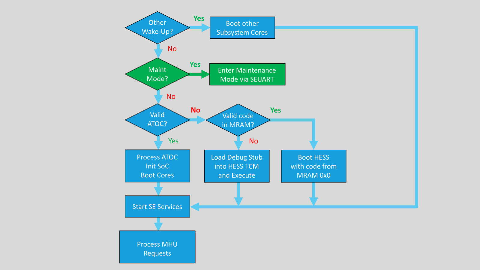
Figure 13: Secure Enclave’s built-in maintenance mode helps recover the device.
The SE checks to see if valid ATOC is present at the end of the MRAM. If yes, the SE processes the information in the ATOC which is used to initialize the MCU and boot up the subsystem cores as specified, including the option for an ATOC signature check.
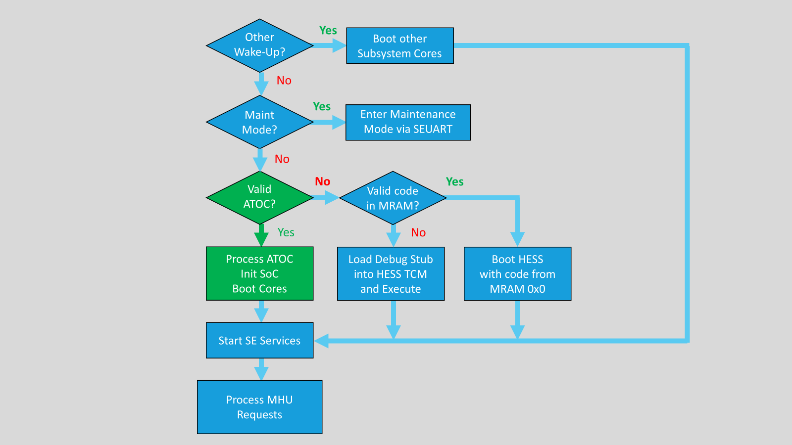
Figure 14: If a valid ATOC is present, the SE uses the ATOC to boot up subsystem cores.
When no ATOC is present in MRAM, the SE will check to see if a valid application is programmed at the beginning of MRAM and will boot the HESS core from MRAM address 0x0.
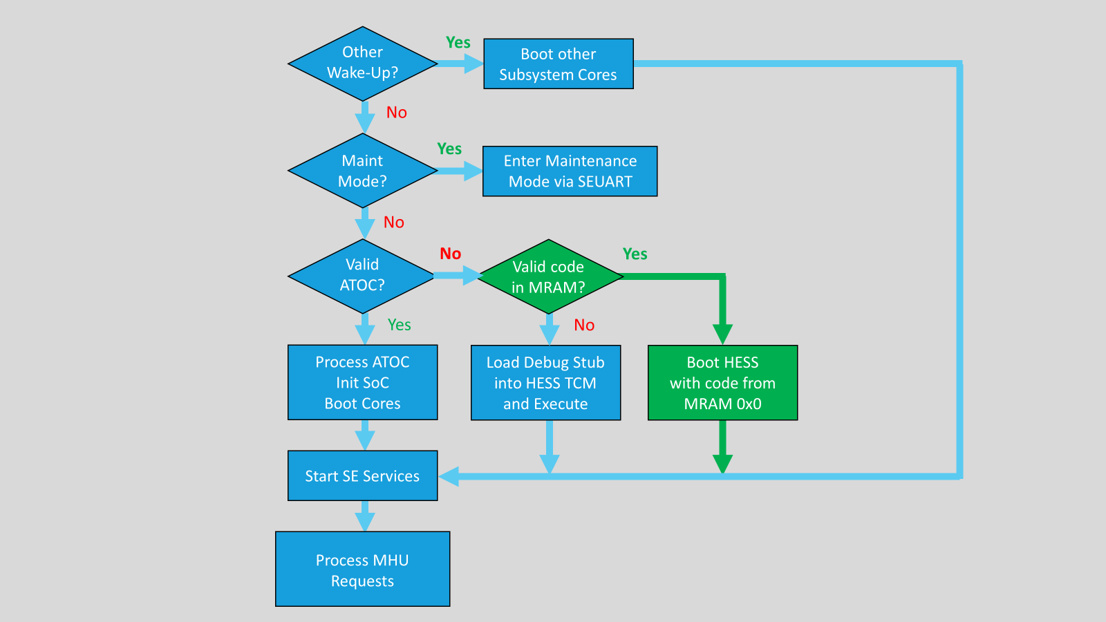
Figure 15: If ATOC is not present, the SE will check for a valid application and then boot the HESS core.
This option is not available in the “Secure” LCS. When no valid application is found at the beginning of the MRAM, the SE will load a debug stub into the TCM memory of the HESS and run it. This allows the customer to connect the debugger to a blank device. This option is also not available in the “Secure” LCS.
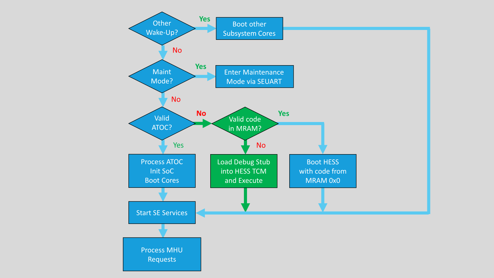
Figure 16: If no valid application is identified at the beginning of MRAM, the SE will load a debug stub into the TCM memory of the HESS.
After this, the Secure Enclave services are started and the application cores request services using an MHU. To learn more about Alif’s secure boot process, please watch this video.
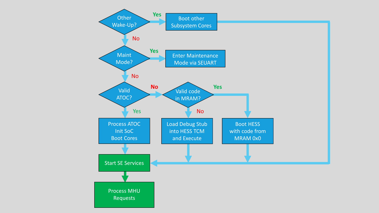
Figure 17: SE services are started and the application cores request services using the MHU.
8. Diminishing Security Threats With Alif Semiconductor
There are already many microcontrollers available that have some of the basic protections such as Root of Trust, key management with random number generators, certificate management, cryptographic acceleration, or decryption of external memory. These often provide protection for only specific types of attacks. However, Alif’s robust security architecture includes unique security services, a flexible configuration matrix, and firewalls that address many of the threats simultaneously; allowing controlled access between different CPUs, memory, and peripherals, to minimize the attack surface and isolate sensitive information. Lifecycle management, that is controlled by the user, further strengthens this security by preventing cloning or rollbacks; protecting the OEM’s IP that might be built into the device.
9. Conclusion
Alif Semiconductor builds security into the architecture of all their processors. The Secure Enclave is a trusted, on-chip platform that has built-in key generation, secure storage, secure boot, cryptographic acceleration, and more. This independent security subsystem also manages the entire lifecycle of the end application from the manufacture, to deployment in the field with secure firmware over-the-air (OTA) updates, and finally to end-of-life. This buffers the MCU from the array of security threats to IoT devices. Alif’s secure and scalable microcontrollers are perfect for a wide range of applications including asset tracking, wearables, AI/ML cameras, EV charging stations, portable medical systems, and more.